
The Physical Anchor: A Primer on Physical Grounding and Spatiotemporal Verification in Autonomous Systems
- Introduction: The Crisis of “Floating” Digital Systems
In classical computer science and software architecture, systems are built upon clean, symbolic mathematical abstractions. In these disembodied environments, identity is represented by an arbitrary string, time is quantified in discrete clock cycles, and data moves instantaneously across code. However, when these unanchored or “floating” digital systems are given operational control over physical infrastructure—such as piloting autonomous vehicles, regulating high-voltage electrical grids, managing subsea pipelines, or controlling smart building enclosures—the abstraction layer breaks down. Disconnected from physical reality, ungrounded software leads to catastrophic operational failures.
When digital ledgers, artificial intelligence swarms, and control loops operate without physical anchors, they expose four critical failure vectors:
- Sybil Identity Duplication: Software identities can be generated at near-zero marginal cost. An adversary can spawn thousands of virtual AI agents in milliseconds, weaponizing voting and resource allocation mechanisms to gain artificial influence and hijack system governance.
- The Spatial Oracle Gap and Relay Attacks: Abstract telemetry streams treat physical data—such as GPS coordinates or temperature metrics—as self-authenticating numbers. Lacking physical verification, cyber-physical access points become vulnerable to Relay Attacks (Mafia/Wormhole Fraud), where authorization signals are tunneled across high-speed optical networks to manipulate a physical lock thousands of kilometers away.
- The Condorcet Inversion in AI Swarms: Synthetic agents built on similar foundation model checkpoints share underlying training corpora, tokenizers, and reinforcement learning alignment criteria. This structural overlap generates positive error covariance (\operatorname{Cov}(v_i, v_j) > 0). When these agents face shared blind spots, gathering more votes mathematically guarantees convergence on collective delusion (\lim_{N \to \infty} P_N = 0) rather than uncovering truth.
- Medium and Electrodynamic Sensor Failures: Software models routinely assume ideal communication channels, ignoring physical constraints—such as electromagnetic interference (EMI) in high-voltage grids, severe radio decay in solid rock, optical scattering underwater, or battery passivation under sub-zero thermal cycling.
To mitigate these systemic vulnerabilities, disembodied digital systems must be replaced by physically grounded cyber-physical architectures:
Ungrounded Digital Systems Grounded Cyber-Physical Stacks
Identity Basis: Disembodied software strings, arbitrary public keys, and virtual LLM agent chaining. Identity Basis: Physical silicon root-of-trust (TPM 2.0 / TEE hardware) with measured boot state.
Trust Model: Purely software-based trust vulnerable to Sybil duplication, key theft, and relay fraud. Trust Model: Relativistic physical invariants governed by the speed of light (c \approx 2.9979 \times 10^8 \text{ m/s}).
Spatial Verification: Abstract scalar telemetry strings subject to the Spatial Oracle Gap and GPS spoofing. Spatial Verification: Multi-static TDoA hyperbolic multilateration and sub-nanosecond UWB distance bounding.
Energy Management: Software sleep states vulnerable to current leakage and latch-up modes. Energy Management: Hard hardware power gating via nano-timers (I_q < 50\text{ nA} off-state switch leakage).
Governance & Risk: Unconstrained majority voting without physical consequences or financial risk. Governance & Risk: Conserved liability models with programmatic 50% staked collateral slashing.
Core Principle: Level 0 (Supreme Ontic Authority)
In a grounded cyber-physical architecture, Level 0 (Supreme Ontic Authority) serves as the ultimate arbiter of truth. This principle mandates that physical sensor telemetry, bounded by the unyielding laws of nature, must always override software models, mathematical proofs, digital ledgers, and multi-agent consensus. When physical reality contradicts a software representation, physical telemetry wins every time.
To prevent software abstractions from failing when deployed in complex environments, systems require an identity framework anchored directly to physical reality.
- Grounding Identity: From Biological Birds to Silicon Trust
To construct an unforgeable identity model for synthetic systems, we can look to biological active-matter physics. Consider a flock of European starlings (Sturnus vulgaris) executing high-speed, coordinated evasive maneuvers against a raptor. Starlings lack serial numbers, IP addresses, or digital certificates, yet thousands of individuals coordinate without a central leader or mid-air collisions.
THE AVIAN KINEMATIC IDENTITY MATRIX
│
├───────────────────────────────────────────────┐
▼ ▼
[SPATIAL HARDCORE EXCLUSION] [TOPOLOGICAL RELATIONAL IDENTITY]
- Mass m_i > 0; Volume V_i > 0 • Starlings track k ≈ 7 neighbors
- Two birds cannot share coordinates • Identity defined by topological rank
- Zero-cost identity creation impossible • Metric distance scales; graph holds
│ │
└───────────────────────┬───────────────────────┘
│
▼
[INERTIAL SPIN WAVE ROLE TRANSFERENCE]
• Initiator Bird banks: Phase change in internal spin s_i
• Torque cascades via J_ij links at c ≈ 20–40 m/s
• “Leader” identity transfers dynamically in milliseconds
Biological swarms resist identity duplication through non-negotiable physical laws:
- Physical Mass and Bodily Volume: Every starling possesses physical mass (m_i \approx 75\text{–}90\text{ g}) and finite volume (V_i > 0). Flying requires continuous metabolic work (P_{\text{aero}} = T \cdot v).
- Hardcore Spatial Exclusion: Two birds cannot occupy the same physical coordinate simultaneously. As the distance r_{ij} between two birds approaches their wingspan limit (d_{\text{wingspan}}), an asymptotic repulsive potential barrier arises (V(r_{ij}) \to \infty). Identity is non-duplicable because physical presence is spatially exclusive.
- Topological Interaction Boundaries (k \approx 7): Empirical studies prove that starlings track a fixed topological number of neighbors (k = 6.5 \pm 0.5 \approx 7) rather than a fixed metric radius. Whether the flock expands during an attack or contracts in transit, each bird maintains awareness relative to seven topological peers, preserving communication channels across density changes.
- Undamped Hyperbolic Inertial Spin Waves: Information moves across the flock not as a slow, diffusive process, but as an undamped second-order wave governed by spin-exchange Hamiltonian mechanics:
\frac{d\mathbf{v}_i}{dt} = \frac{1}{\chi_0} \mathbf{s}_i \times \mathbf{v}i, \quad \frac{d\mathbf{s}i}{dt} = \sum{j \in S_i} J{ij} \left( \mathbf{v}_i \times \mathbf{v}_j \right) – \frac{\eta_0}{\chi_0} \mathbf{s}_i
Where \mathbf{s}i represents internal spin (rotational generator), \chi_0 is rotational inertia, and J{ij} is alignment stiffness. Directional changes ripple across the flock at sound-wave velocities (\omega = c \cdot k \approx 20\text{–}40\text{ m/s}), faster than individual physiological reaction times (>100\text{ ms}). “Leadership” is a temporary role that passes instantly to whichever bird detects a boundary threat first.
In contrast, disembodied AI agents deployed on generic server infrastructure face the Zero-Marginal-Cost Identity Catastrophe. Because creating a digital identity costs virtually nothing, an adversary can instantiate 100,000 Large Language Model (LLM) agents in seconds. If governance or resource allocation uses Quadratic Voting (where influence scales as \sum \sqrt{c_i}), splitting capital C across K fake identities inflates an attacker’s influence by a factor of \sqrt{K}:
\sum_{i=1}^K \sqrt{\frac{C}{K}} = K \cdot \sqrt{\frac{C}{K}} = \sqrt{K \cdot C} = \sqrt{K} \cdot \sqrt{C}
To solve this vulnerability, we bridge physical intuition to digital architecture. A single software key is insufficient because keys can be cloned across virtual machines without physical footprint. The Resilient Epistemic & Thermodynamic Ledger Architecture (RELA) grounds synthetic identity in a multi-dimensional tuple (\text{ID}_i):
\text{ID}i = \left\langle \sigma{\text{TPM}}, ; \theta_i, ; \mathcal{H}_{\text{weights}}, ; \text{BS}k, ; W_i, ; \mathcal{S}{\text{FEP}} \right\rangle
THE RELA SYNTHETIC IDENTITY TUPLE
ID_i = ⟨ σ_TPM , θ_i , H_weights , BS_k , W_i , S_FEP ⟩
│ │ │ │ │ │
┌────────┘ │ │ │ │ └────────┐
▼ ▼ ▼ ▼ ▼ ▼
[HARDWARE ROOT] [FRAME] [WEIGHTS] [BRIER] [STAKE] [ACTIVE INFERENCE]
- TPM 2.0 Silicon • Π_θ • Disjoint • Historical • Escrowed • Variational Free
- Measured Boot • Low-d Training Calibration Collateral Energy F & Landauer
- Non-exportable Frame Checksum Vector Subject to 50% Erasure Joules
Key (Ed25519) Slashing Metering - \sigma_{\text{TPM}} (Hardware Silicon Root): A non-exportable cryptographic signature generated within a physical Trusted Execution Environment (TEE) or TPM 2.0 microchip embedded on a local compute blade. So What? (System Benefit): Binds the software agent directly to physical silicon registers, preventing virtualization cloning and requiring attackers to physically buy hardware to scale identities.
- \theta_i (Perspectival Frame ID): The SHA-256 hash of the agent’s declared observation boundaries, sensor sensitivities, coordinate origins, and prompt constraints (\hat{\Pi}{\theta_i}: \mathcal{M} \to \mathcal{P}{\theta_i}). So What? (System Benefit): Explicitly bounds what the agent can observe and claim within its low-dimensional projection plane, preventing uncalibrated claims outside its domain.
- \mathcal{H}{\text{weights}} (Disjoint Checkpoint Provenance): The cryptographic hash of the foundational neural network weights (\operatorname{SHA256}(\mathbf{W}{\text{model}})). So What? (System Benefit): Mitigates common-mode failure; consensus rules collapse agents sharing identical weight hashes into a single vote to neutralize hidden biases.
- \text{BS}_k (Historical Brier Reputation Vector): The empirical track record of forecast calibration across specific operational domains (\mathcal{D}k), calculated as \text{BS}{i,k} = \frac{1}{N} \sum (f_t – o_t)^2 \in [0,2]. So What? (System Benefit): Automatically reduces the voting weight of uncalibrated or hallucinating agents based on verifiable historical performance.
- W_i (Staked Compute Collateral): Escrowed capital or compute tokens locked on-chain. So What? (System Benefit): Enforces economic accountability by subjecting the collateral to programmatic slashing if a physical failure occurs.
- \mathcal{S}_{\text{FEP}} (Active Inference Thermodynamic State): Runtime telemetry tracking internal Variational Free Energy (F) and Landauer heat dissipation (\Delta Q). So What? (System Benefit): Metering computational heat prevents agents from entering infinite, energy-wasting reflection loops.
To enforce these hardware bounds without revealing proprietary model weights or private keys, candidate nodes pass through a Zero-Knowledge Admission Pipeline. Before entering a consensus quorum, an agent derives a deterministic nullifier using an algebraic hash:
\mathcal{H}{\text{null}} = \operatorname{Poseidon}(S{\text{TPM}}, \text{Epoch}_T)
The agent then generates a zero-knowledge proof (\pi_{\text{div}} using Groth16 or PLONK circuits) attesting that its TPM attestation quote is valid, its nullifier was correctly derived from its non-migratable secret S_{\text{TPM}}, and its neural weight distance relative to active swarm weights meets an architectural diversity threshold (\mathcal{D}(\vec{w}{\text{candidate}}, \vec{w}{\text{swarm}}) \ge \delta_{\text{diversity}}). The BFT consensus layer checks whether \mathcal{H}_{\text{null}} exists in an on-chain nullifier tree; if present, the attempt is rejected as a duplicate hardware Sybil attempt.
Dimension Biological Starling Swarms (Sturnus vulgaris) Synthetic Agent Swarms (RELA Stacks)
Ontological Basis Kinematic state vector & mass (m_i > 0, V_i > 0). Relational Epistemic Tuple (\text{ID}i = \langle \sigma{\text{TPM}}, \theta_i, \mathcal{H}_{\text{weights}}, \text{BS}k, W_i, \mathcal{S}{\text{FEP}} \rangle).
Anti-Sybil Mechanism Hardcore spatial exclusion (V > 0) & aerodynamic inertia. Hardware TPM 2.0 silicon attestation, ZK-nullifier trees, and Landauer erasure costs.
Interaction Boundary Topological rank-order (k \approx 7 neighbors). Epistemic task routing via Softmax over inverse Brier calibration (\text{BS}_k).
Role Transference Inertial spin-wave phase handoff (\omega = c \cdot k). Liquid Epistemic Delegation with automatic 50% cryptographic stake slashing.
Terminal Failure Mode Spatial rupture & panic splits from uncoordinated evasion. Sybil swarm takeover, context bloat, and model collapse via shared weights.
Connecting physical hardware identity to location requires measuring physical space and distance through verifiable laws of physics.
- Spatiotemporal Verification: Anchoring Time and Space with Physics
Autonomous systems must verify both where an asset is located (macro-spatial location) and whether two entities are physically co-present (micro-relational proximity). Rather than trusting unauthenticated software reports, systems can transform spatial claims into physical invariants governed by the speed of light (c \approx 2.9979 \times 10^8 \text{ m/s}). Signal propagation velocity in any physical medium with permittivity \epsilon and permeability \mu is bounded by c:
v = \frac{1}{\sqrt{\epsilon \mu}} \le c
Spatiotemporal verification relies on two complementary physical pillars:
THE DUAL SPATIAL PARADIGM
┌───────────────────────────────────────────────────────────────────────────────────┐
│ 1. PROOF OF LOCATION (PoL): MACRO-SPATIAL ANCHOR │
│ • Reference Frame: Absolute (ECEF coordinates: x, y, z, t). │
│ • Physical Mechanism: Multi-party TDoA, carrier-phase multilateration, GNSS. │
│ • Question Answered: “Where in the physical universe is this node located?” │
│ • Governance Role: Validates DePIN asset deployment and regional jurisdiction. │
└─────────────────────────────────────────┬─────────────────────────────────────────┘
│ Bound & Constrained by
▼
┌───────────────────────────────────────────────────────────────────────────────────┐
│ 2. PROOF OF PROXIMITY (PoP): MICRO-RELATIONAL BOUNDARY │
│ • Reference Frame: Relative / Relational (Distance metric: d ≤ d_max). │
│ • Physical Mechanism: IEEE 802.15.4z UWB Round-Trip Time-of-Flight (ToF). │
│ • Question Answered: “Is this agent physically co-present with entity X?” │
│ • Governance Role: Prevents relay attacks on smart locks; bounds swarm meshes. │
└─────────────────────────────────────────┴─────────────────────────────────────────┘
3.1 Macro-Spatial Anchoring: Proof of Location (PoL)
Proof of Location verifies absolute geographic coordinates (\mathbf{x} \in \mathbb{R}^3). In Denied, Degraded, Intermittent, or Limited (DDIL) environments—or under active Electronic Warfare (EW) where civilian GPS signals (-160\text{ dBW}) are easily spoofed—PoL utilizes multi-static Time Difference of Arrival (TDoA) multilateration across fixed mesh anchors (\mathbf{s}_i, \mathbf{s}_j).
When a mobile node transmits a radio packet, stationary anchors record the precise picosecond Time of Arrival (t_i, t_j). The true coordinate \mathbf{x} must satisfy the hyperbolic range difference equations:
\Delta d_{ij} = c \cdot (t_i – t_j) = |\mathbf{x} – \mathbf{s}_i|_2 – |\mathbf{x} – \mathbf{s}_j|_2
If the mathematical solution from TDoA deviates from the location reported by the node’s onboard telemetry beyond an error threshold (\tau_{\text{spatial}}), an ontic spatial breach is flagged, and the false claim is rejected.
3.2 Micro-Relational Boundaries: Proof of Proximity (PoP)
While PoL answers where a node is on a map, Proof of Proximity (PoP) answers whether two entities are physically next to each other. This is crucial for securing physical access points—such as smart locks, microgrid charging docks, or vehicle doors—against Relay Attacks (Mafia/Wormhole Fraud). In a relay attack, an adversary captures short-range wireless tokens from an authorized user far away and tunnels them over high-speed networks to unlock a door without the user being physically present.
PoP neutralizes this using IEEE 802.15.4z Ultra-Wideband (UWB) sub-nanosecond Round-Trip Time-of-Flight (ToF) distance bounding:
- The verifier (e.g., a smart lock) sends a pseudorandom cryptographic challenge bit sequence c_i at time t_0.
- The prover’s hardware TPM 2.0 / UWB transceiver reflects the response sequence r_i at time t_1.
- The verifier measures the total round-trip time: \Delta t = t_1 – t_0 – t_{\text{proc}}, where t_{\text{proc}} is the calibrated silicon processing delay.
- Physical distance is bounded by d \le \frac{c \cdot \Delta t}{2}.
[ ADVERSARIAL RELAY ATTACK (MAFIA FRAUD) ON LEGACY SMART LOCK ]
[ Real Traveler Token ] ──(BLE/NFC)──► [ Attacker A ] ══ HIGH-SPEED FIBER ══► [ Attacker B ] ──(Emulated Key)──► [ Smart Door Lock ]
(Remote Location) (Long Distance) (Physical Asset)
Result: Door unlocks fraudulently; physical distance assumption violated.
[ DEFENSE: DISTANCE-BOUNDING PROOF OF PROXIMITY (PoP) ]
[ Legitimate Prover (TPM 2.0) ] [ Physical Verifier (Lock) ]
│ │
│ ◄────────────────────── Challenge Bit Sequence c_i ──────────────────────────────┤ (Time t_0)
│ │
├─────────────────────── Rapid Response Bit Sequence r_i ─────────────────────────► │ (Time t_1)
│ │
Calculation: Δt = t_1 – t_0 – t_proc ===> d ≤ (c · Δt) / 2
Result: Information cannot travel faster than c; relay across long distance causes Δt to explode.
Step-by-Step Mathematical Derivation: UWB Proximity Bound
To understand why relay attacks fail, we compute the maximum allowable delay budget for a 2.0\text{ meter} physical proximity boundary.
- Define the Physical Parameters:
- Target maximum distance: d_{\text{max}} = 2.0\text{ meters}
- Propagation speed in air: c = 299,792,458\text{ m/s}
- Formulate the Round-Trip Signal Path:
- A signal must travel 2.0\text{ m} to the prover and 2.0\text{ m} back to the verifier, yielding a total physical path length of 2 \cdot d_{\text{max}} = 4.0\text{ meters}.
- Calculate the Maximum Allowable Round-Trip Time (\Delta t_{\text{max}}): \Delta t_{\text{max}} = \frac{2 \cdot d_{\text{max}}}{c} = \frac{2 \cdot 2.0\text{ m}}{2.99792458 \times 10^8\text{ m/s}} = 1.334256 \times 10^{-8}\text{ s} \approx 13.34\text{ nanoseconds}
- Engineering Conclusion: If an attacker attempts to relay the challenge signal through a fiber-optic, cellular, or network tunnel across a distance of even 1\text{ km}, the additional propagation delay (\Delta t_{\text{tunnel}} \ge \frac{2 \cdot 1000\text{ m}}{3 \times 10^8\text{ m/s}} \approx 6.67\ \mu\text{s}) plus network switching jitter adds microseconds of latency. Because 6,670\text{ ns} \gg 13.34\text{ ns}, the measured time budget explodes, tripping the hardware circuit breaker and denying access.
Category Proof of Location (PoL) Proof of Proximity (PoP)
Reference Frame Absolute global frame (ECEF / WGS84 coordinates: x, y, z, t). Relative / Relational local frame (d \le d_{\max}).
Physical Mechanism Multi-party TDoA hyperbolic multilateration & Doppler tracking. IEEE 802.15.4z UWB sub-nanosecond Round-Trip Time-of-Flight.
Core Question Answered “Where in the physical universe is this node located?” “Is this agent physically co-present with entity X?”
Governance Role Validates physical DePIN asset deployments & regional jurisdictions. Neutralizes relay attacks on smart locks; bounds swarm meshes.
These physical invariants must be designed to withstand demanding real-world operating environments.
- Mastering the Medium: Deploying Pervasive Sensors in Extreme Environments
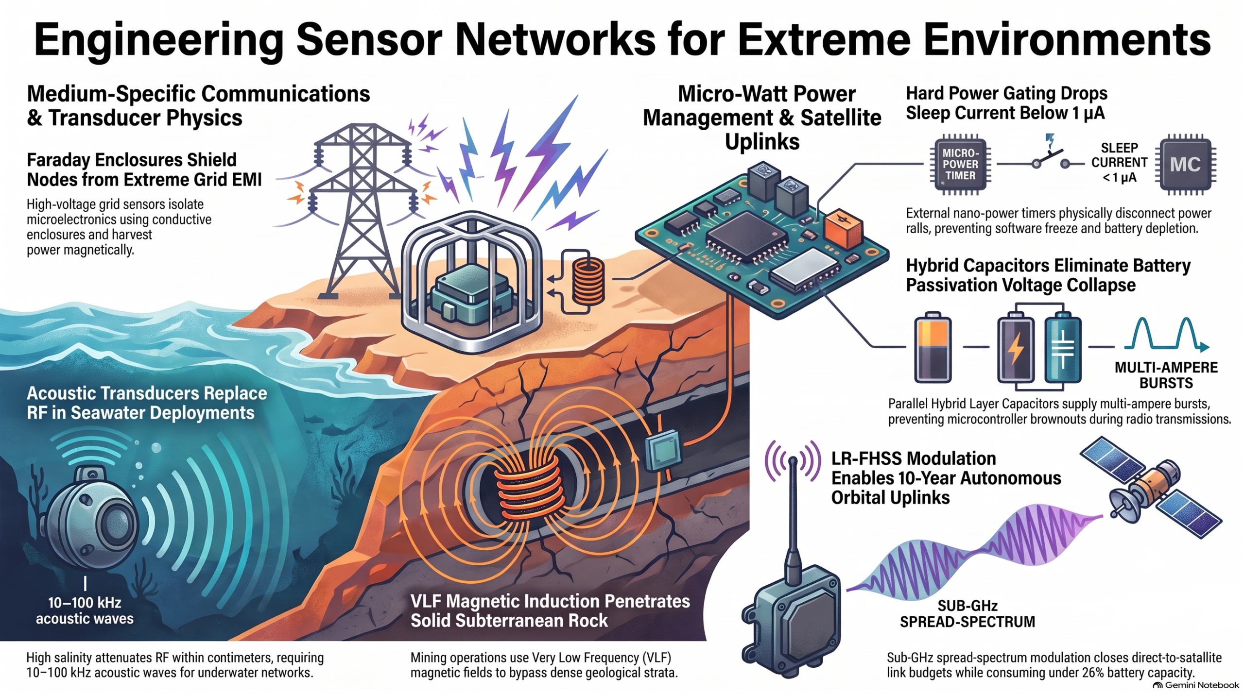
Deploying physical sensor networks across extreme real-world environments requires navigating strict electrodynamic and thermodynamic engineering constraints. Physical mediums shape node hardware design, battery chemistry, and transmission protocols across a Four-Tier Architecture:
+───────────────────────────────────────────────────────────────────────────────────+
│ FOUR-TIER WSN/EDGE STACK │
+===================================================================================+
│ TIER 4: APPLICATION & DIGITAL TWIN LAYER │
│ – Real-time SCADA / Enterprise Historians – Physics-Informed Digital Twins │
│ – Actuation Engines & Closed-Loop Control Orchestrators │
+───────────────────────────────────────────────────────────────────────────────────+
▲ RESTful APIs, gRPC, OPC-UA, AMQP
+───────────────────────────────────────────────────────────────────────────────────+
│ TIER 3: MIDDLEWARE, FOG & CLOUD PROCESSING LAYER │
│ – Stream Ingestion (Kafka, MQTT Brokers) – Distributed State Storage │
│ – Containerized Microservices – OTA Firmware Management │
+───────────────────────────────────────────────────────────────────────────────────+
▲ IP Backbone, 5G NR/C-V2X, LEO Satellite, Fiber
+───────────────────────────────────────────────────────────────────────────────────+
│ TIER 2: NETWORK & ROUTING LAYER │
│ – Deterministic Mesh Topologies (TSCH, RPL, 6LoWPAN, LoRaWAN, Wi-SUN) │
│ – Media Access Control (MAC) Scheduling, Channel Hopping, Collision Avoidance │
│ – Delay-Tolerant Networking (DTN) & Acoustic Depth-Based Forwarding │
+───────────────────────────────────────────────────────────────────────────────────+
▲ Baseband / RF / Acoustic / Quasi-Magnetostatic
+───────────────────────────────────────────────────────────────────────────────────+
│ TIER 1: PERCEPTION & PHYSICAL COMPUTING LAYER (WSN NODE) │
│ – Transducers (Piezoresistive, Capacitive, Electrochemical, Optical) │
│ – Analog Front-End (AFE): Instrumentation Amplifiers (CMRR > 100 dB) │
│ – Mixed-Signal Digitization: SAR / Delta-Sigma ADCs │
│ – Compute Engine: MCUs with Hardware Crypto & Power Management │
+───────────────────────────────────────────────────────────────────────────────────+
4.1 High-Voltage Smart Grids
Power transmission lines (115\text{ kV} to 765\text{ kV}) generate extreme Electromagnetic Interference (EMI), high electrostatic fields (E > 2\text{–}3\text{ MV/m}), and transient switching surges with slew rates exceeding \frac{dV}{dt} > 100\text{ kV}/\mu\text{s}.
Line-Mounted High-Voltage Node Architecture
PHASE CONDUCTOR (69 kV to 765 kV RMS, I_load = 20 A to 40 kA Fault)
══════════════════════════════════════════════════════════════════════════════════
│
▼ Mechanical Clamping Interface
+──────────────────────────────────────────────────────────────────────────────+
│ EQUIPOTENTIAL FARADAY ENCLOSURE (Cast Aluminum Shell, Rounded R > 15 mm) │
│ Waveguide-Below-Cutoff Ports (d < λ/10, l/d ≥ 3) │
│ │
│ [ Energy Harvesting Stage ] │
│ Split-Core Nanocrystalline CT ──► Active MOSFET Shunt ──► Rectifier ──► PMIC │
│ (Triac Crowbar Array clamps in nanoseconds during 40 kA line faults) │
│ │
│ [ Microelectronics Chamber ] │
│ Secondary Mu-Metal Shield (μ_r > 50,000) │
│ Isolated Power Rails (CMTI > 150 kV/µs) │
│ ARM Cortex-M33 Core + Wi-SUN Sub-GHz Radio │
+────────────────────────────────────────────┬─────────────────────────────────+
│ External RF Port (DC-Isolated)
▼
[ Corona-Suppressed Monopole Antenna ]
- Mitigation Strategy: Nodes use an equipotential “Bird-on-a-Wire” chassis clamped directly to live conductors, allowing microelectronics to float at line potential inside a cast aluminum Faraday shield. Antenna openings use Waveguides-Below-Cutoff (WBC) with an aspect ratio of \ell/d \ge 3, yielding attenuation exceeding \alpha_{\text{dB}} \approx 27.3 \cdot \frac{\ell}{d} > 80\text{ dB} to block internal EMI.
- Power Harvesting: Nodes power themselves by harvesting energy from the conductor’s magnetic field using split-core current transformers (CTs). To survive 40\text{ kA} short-circuit fault surges, the CT secondary uses an active high-speed MOSFET shunt and triac crowbar array to short the winding in nanoseconds, collapsing excess internal magnetic flux.
4.2 Subterranean Mining & Geotechnical Engineering
In underground mining, radio signals at high frequencies (2.4\text{ GHz}) fail due to skin-depth attenuation in conductive rock (\sigma = 10^{-2}\text{ S/m}), experiencing severe signal loss (\alpha \approx 1,337\text{ dB/m}):
\alpha = \sqrt{\pi f \mu \sigma} \quad [\text{Np/m}]
- Mitigation Strategy: Systems use Through-The-Earth (TTE) low-frequency quasi-magnetostatic induction operating in Very Low Frequency (VLF: 3\text{–}30\text{ kHz}) or Extremely Low Frequency (ELF: 300\text{ Hz}\text{–}3\text{ kHz}) bands. At 1\text{ kHz}, signal attenuation drops to 0.054\text{ dB/m}, allowing low-bandwidth magnetic telemetry to penetrate hundreds of meters of solid rock.
- Explosive Atmosphere Safety: Flammable methane (\text{CH}4) and coal dust require Intrinsically Safe (Ex ia) hardware. Electrical energy stored in onboard capacitors and inductors must be capped (E{\text{spark}} \le 150\ \mu\text{J}) so that a component failure cannot produce a spark capable of causing an explosion.
4.3 Subsea Acoustic Sensor Networks (UWSNs)
High salinity makes seawater conductive (\sigma \approx 4\text{ S/m}), attenuating high-frequency radio waves within centimeters (\approx 34.5\text{ dB/m} at 1\text{ MHz}). Optical signals scatter rapidly due to suspended organic particles, limiting visibility to short ranges (<10\text{–}20\text{ meters}).
- Mitigation Strategy: Underwater networks rely on acoustic pressure waves (10\text{ kHz} to 100\text{ kHz}) driven by Tonpilz piezoceramic transducers.
- Network Dynamics: Sound travels through seawater at roughly 1,500\text{ m/s}—five orders of magnitude slower than light (3 \times 10^8\text{ m/s}). This long propagation delay makes standard CSMA/CA MAC protocols impractical. Networks use Depth-Based Routing (DBR), where nodes use pressure sensors to calculate their physical depth and compute localized forwarding holding delays (t_{\text{hold}}):
t_{\text{hold}} = \tau_{\text{max}} \cdot \left(1 – \frac{\Delta z}{R_{\text{range}}}\right)
The shallowest node broadcasts first, while deeper competitors overhear the transmission and cancel their redundant timers.
4.4 Wilderness Disaster Mitigation
Wilderness nodes deployed for early fire or flood detection must operate unattended for 5 to 10+ years without mains power or solar panels under dense forest canopies.
HIERARCHICAL POWER-GATED SUBSYSTEM ARCHITECTURE
[ Primary Li-SOCl2 Cell ] ──> [ Hybrid Layer Cap (HLC) ] ──> Direct Rail (Unregulated 3.6 V)
│
┌─────────────────────────────────────────────────────────────────┴────────┐
│ │
▼ (Continuous Low Quiescent Rail, Load Switch Reverse Leakage < 10 nA) ▼
+────────────────────────────────────────────+ Active High-Side Load Switches (P-MOSFETs)
| Nano-Power System Timer (e.g., TPL5110) | (Off State Leakage < 10 nA; System Iq < 50 nA)
| – Draws 35 nA continuous | ├── Power Rail 1 ──> [ Sensors & AFEs ]
| – External Analog Wake Thresholds | ├── Power Rail 2 ──> [ Main MCU Core ]
| – Drives EN pins of Main Power Gates | └── Power Rail 3 ──> [ Satellite RF PA / Tx ]
+────────────────────────────────────────────+
- Power Management Architecture: Nodes maintain an aggregate target sleep profile of I_{\text{sleep}} \le 500\text{ nA}. To clarify component power profiles: while the overall system sleep baseline is under 500\text{ nA}, individual high-side load switches achieve off-state reverse leakage currents of I_q < 50\text{ nA} (e.g., TPS22916 at <10\text{ nA}), while the nano-power system timer (TPL5110) draws just 35\text{ nA}. External nano-power timers disconnect system power rails using these low-leakage P-MOSFET load switches, waking the main processor only for scheduled heartbeats or threshold alerts.
- Battery Passivation & Buffer Solutions: Nodes use primary Lithium Thionyl Chloride (\text{Li-SOCl}2) cells due to their energy density (>650\text{ Wh/kg}) and multi-decade shelf life. However, \text{Li-SOCl}2 forms a protective lithium chloride (\text{LiCl}) passivation layer that increases internal resistance. When a node requests a 1\text{–}2\text{ A} pulse to transmit to a Low-Earth Orbit (LEO) satellite, this resistance drops terminal voltage (V{\text{terminal}} = V{\text{OCV}} – I_{\text{pulse}} \cdot R_{\text{passivation}}), triggering a brownout reset. Systems resolve this by wiring a Hybrid Layer Capacitor (HLC) in parallel with the battery. The primary cell trickles power into the HLC during sleep, and the HLC delivers high-current pulses during satellite transmissions.
THE BATTERY PASSIVATION VOLTAGE COLLAPSE & HLC BUFFER
Terminal Voltage
3.6 V ┌──────────────────────────────────────────────┐
│ │
3.0 V ├──────┐ │
│ │ VOLTAGE DELAY DROP │
2.2 V ├──────┼───────────────────────┐ │
│ │ (MCU Brownout Window) │ │
1.8 V ├──────┴───────────────────────┼───────────────┴── Safe Level (Post-Depassivation)
│ │
└──────────────────────────────┴────────────────── Time (ms)
[ Primary Li-SOCl2 Bobbin Cell ] (High Energy Density, Low Continuous Current: 10–50 mA)
│
├───────────────────────────────────────────────┐
│ Continuous Micro-Current Trickle Charge │
▼ ▼
[ Hybrid Layer Capacitor (HLC) ] [ Low-Leakage System Rail ]
(Low ESR < 100 mΩ, Pulse Output: 2–5 A)
│ │
└───────────────────────┬───────────────────────┘
│
▼
[ High-Power Satellite PA ]
Direct-to-Satellite Link Budget Model (LEO Sub-GHz at 868 MHz)
To demonstrate how a battery-powered wilderness node closes a wireless link with an orbital satellite 800\text{ km} above the Earth without high-gain tracking dishes, we construct the Friis transmission link budget:
P_{\text{rx}} = P_{\text{tx}} + G_{\text{tx}} + G_{\text{rx}} – \text{FSPL} – L_{\text{atm}} – L_{\text{pol}} – L_{\text{fade}}
Where Free Space Path Loss (\text{FSPL}) at slant range d = 800\text{ km} and frequency f = 868\text{ MHz} is calculated as:
\text{FSPL}{\text{dB}} = 20\log{10}(d) + 20\log_{10}(f) + 20\log_{10}\left(\frac{4\pi}{c}\right) \approx 149.30\text{ dB}
Link Budget Parameter Value Notes / Engineering Description
Transmit Power Output (P_{\text{tx}}) +22.00\text{ dBm} 158\text{ mW} output generated by onboard GaAs PA.
Transmit Antenna Gain (G_{\text{tx}}) +2.15\text{ dBi} Omnidirectional half-wave dipole antenna.
Free Space Path Loss (\text{FSPL}) -149.30\text{ dB} 800\text{ km} slant range at 868\text{ MHz} carrier frequency.
Atmospheric & Absorption Losses (L_{\text{atm}}) -0.50\text{ dB} Clear-air path attenuation below 1\text{ GHz}.
Polarization Mismatch Loss (L_{\text{pol}}) -3.00\text{ dB} Linear dipole ground node transmitting to RHCP satellite array.
Ionospheric Scintillation & Fade Margin (L_{\text{fade}}) -3.00\text{ dB} Margin allocation for solar flare activity and canopy shadows.
Satellite Receive Antenna Gain (G_{\text{rx}}) +6.00\text{ dBi} Orbital phased array on LEO satellite.
Total Received Power at Satellite (P_{\text{rx}}) -125.65\text{ dBm} Calculated signal power arriving at LEO receiver front-end.
Satellite Receiver Sensitivity (LR-FHSS) -137.00\text{ dBm} Sensitivity threshold for low-rate frequency hopping spread spectrum.
Net Operating Link Margin +11.35\text{ dB} Positive Link Margin: Guarantees reliable orbital uplink.
Sector Primary Transmission Medium Propagation Velocity Dominant Physical Hazard Engineering Mitigation Strategy
High-Voltage Grids Sub-GHz RF, 5.8 GHz, Optical Fiber \approx 3 \times 10^8\text{ m/s} Extreme EMI, dV/dt > 100\text{ kV}/\mu\text{s} surges, corona RFI Faraday shielding, Waveguides-Below-Cutoff, split-core CT harvesting
Subterranean Mining Quasi-Magnetic Induction (TTE VLF/ELF) \approx 3 \times 10^8\text{ m/s} Rock skin-depth loss (1,337\text{ dB/m} at 2.4 GHz), explosion risks Low-frequency TTE magnetic induction, Intrinsic Safety (E_{\text{spark}} \le 150\ \mu\text{J})
Wilderness Mitigation Sub-GHz RF, LEO Satellite (LR-FHSS) \approx 3 \times 10^8\text{ m/s} Deep freeze (-40^\circ\text{C}), canopy shadows, battery passivation Hard hardware power gating (I_q < 50\text{ nA} switches), \text{Li-SOCl}_2 + HLC buffer
Marine Systems (UWSN) Subsea Acoustic Pressure Waves \mathbf{\approx 1,500\text{ m/s}} Seawater RF decay (34.5\text{ dB/m}), high pressure, biofouling Tonpilz piezoceramic transducers, Depth-Based Routing (DBR)
Understanding physical environmental limits allows us to design governance systems that enforce accountability when failures occur.
- Governance, Liability, and Epistemic Convergence
Grounded cyber-physical systems process truth and enforce accountability by linking digital authority directly to physical liability.
In traditional delegation systems, representatives are insulated from the consequences of their actions. Under RELA’s Conserved Liability model, financial and operational risk travels along the exact same channel as delegated authority. Furthermore, grounded systems discover truth not by collecting affirmative votes, but through the Via Negativa—the systematic, measure-theoretic elimination of falsified parameter space:
\Theta_{t+1} = \Theta_t \setminus \left{ \theta \in \Theta_t : S(E_t, \theta) > \tau_t \right}
Where \Theta_0 is a compact hypothesis space with measure \mu(\Theta_0) = 1.0. As Level 0 telemetry events (E_t) reveal discrepancy loss statistic violations (S(E_t, \theta) > \tau_t), falsified regions are excised (\mu(\Theta_{t+1}) \le \mu(\Theta_t) and \frac{d\mu(\Theta)}{dt} \le 0). Under conditions of identifiability, the Borel-Cantelli Lemma guarantees that the true physical parameter state \theta^* = \hat{\Pi}(\Omega^) is preserved almost surely (P(\theta^ \in \bigcap_{t=0}^\infty \Theta_t) = 1), while the volume of plausible false claims contracts toward the physical measurement noise limit \epsilon.
When physical sensor audits detect a breach of real-world boundaries (S(E_t, \theta) > \tau_t), the system executes an automated penalty workflow:
THE LIQUID EPISTEMIC DELEGATION & SLASHING WORKFLOW
┌───────────────────────────────────────────────────────────────────────────────────┐
│ Delegator Nodes (A1, A2, A3) │
│ Delegate voting weight to Domain Specialist B │
└─────────────────────────────────────────┬─────────────────────────────────────────┘
│
▼
┌───────────────────────────────────────────────────────────────────────────────────┐
│ Delegate Node B exercises combined weight: W_total = ∑ W_i │
│ Signs Policy Proposal Manifest with empirical discrepancy threshold τ_t │
└─────────────────────────────────────────┬─────────────────────────────────────────┘
│
▼
┌───────────────────────────────────────────────────────────────────────────────────┐
│ Level 0 Sensor Audit at Epoch t + Δt │
│ Empirical Discrepancy Calculated: S(E_t, θ) │
│ │
│ [ S(E_t, θ) ≤ τ_t ] [ S(E_t, θ) > τ_t ] │
│ │ │ │
│ ▼ ▼ │
│ SUCCESSFUL SETTLEMENT CRITICAL FAILURE BREACH │
│ • Delegate receives +15% yield • Delegate B slashed 50% │
│ • Delegators receive yield dividend • Curators slashed 25% │
│ • Brier reliability improves • ALL DELEGATIONS SEVERED │
│ • Power snaps back to A_i │
└───────────────────────────────────────────────────────────────────────────────────┘
Operational Sequence: Hierarchical Transitive Slashing Workflow
- Primary Executor Penalty:
- The executing node directly responsible for signing the failed operational directive incurs an immediate 50% cryptographic burn of its escrowed capital (W_i).
- Curation and Routing Penalty:
- Intermediate nodes that routed, curated, or endorsed the delegate incur an automatic 25% stake slash for poor delegation curation.
- Sponsoring Originator Penalty:
- The original sponsoring entity that instantiated the delegation chain suffers a 10% risk deduction on its staked balance.
- Instant Snap-Back Reversion Circuit:
- The delegation graph is severed at the firmware and ledger layers. Active capability tokens are revoked, physical actuators lock into safe configurations at the hardware layer, and remaining unslashed voting power snaps back to self-custody.
Thermodynamic Bound: Landauer’s Principle and the Metabolic Halting Gate
According to Landauer’s Principle, erasing or overwriting N bits of information in any physical compute device dissipates a fundamental minimum amount of thermal heat into the environment:
\Delta Q \ge N \cdot k_B T \ln 2
Where k_B = 1.380649 \times 10^{-23}\text{ J/K} is the Boltzmann constant and T is temperature in Kelvin. Artificial intelligence reflection loops can fall into Infinite Metacognitive Regress (deliberating indefinitely without improving certainty). Grounded architectures implement a Metabolic Halting Gate at the hardware layer. This gate continuously evaluates expected Variational Free Energy reduction (\Delta F) against physical thermodynamic heat dissipation (\Delta Q):
\text{If } \Delta F < \lambda \cdot \Delta Q, \quad \text{Trigger: } \operatorname{FORCE_ACTION_HALT}
Here, \lambda = 1.25 represents the minimum informational efficiency parameter governing expected Free Energy reduction relative to heat dissipation. If an AI agent cannot prove that an additional reflection cycle yields an informational gain (\Delta F) at least 1.25 times greater than its physical energy cost (\Delta Q), computation is halted at the silicon layer.
By anchoring digital identities, spatial telemetry, and consensus protocols in the unyielding laws of physical nature—from special relativity and electrodynamics to non-equilibrium thermodynamics—cyber-physical systems eliminate vulnerabilities born of digital abstraction, creating resilient, self-correcting autonomous networks grounded in physical reality.


