
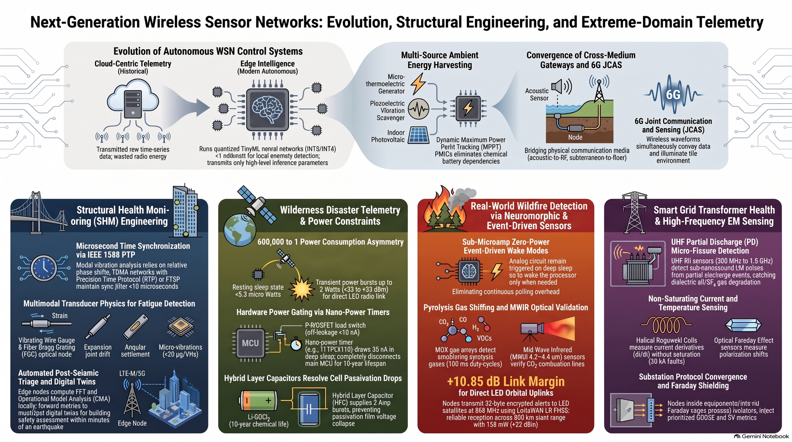
Comprehensive Engineering Guide for Direct-to-Satellite Deep-Sleep Telemetry in Remote Wilderness Disaster Monitoring
- Architectural Framework for Multi-Year Autonomous Wilderness Nodes
Autonomous sensor nodes deployed in unserviced wilderness environments face unforgiving operational demands. Natural hazard monitoring—such as early detection of wildland fires, sudden flash floods, volcanic activity, and alpine slope failures—requires deploying hardware across remote watersheds, mountain passes, and dense forest canopies. These regions lack electrical power grids, cellular infrastructure, and physical accessibility. Traditional terrestrial mesh topographies and localized cellular gateways fail in these environments due to severe topographic obstruction, non-line-of-sight terrain profiles, and dense vegetative canopy attenuation. Consequently, each sensing node must operate as an independent, standalone telemetry terminal capable of establishing direct uplinks to orbital satellite constellations while functioning within a strict micro-watt power budget.
+————————————————————————————————-+
| Hierarchical Power-Gated Subsystem Architecture |
| |
| [ Primary Li-SOCl2 Cell ] ──> [ Hybrid Layer Cap (HLC) ] ──> Direct Rail (Unregulated 3.6 V) |
| │ |
| ┌─────────────────────────────────────────────────────────────────┴────────┐ |
| │ │ |
| ▼ (Continuous Low Quiescent Rail via Buck Converter, Iq = 60 nA) ▼ |
| +——————————————–+ Active High-Side Load Switches (P-MOSFETs) |
| | Regulated 2.5 V Always-On Nano-Logic Rail | (TPS22916, Off-State Leakage < 10 nA) |
| | – Nano-Power System Timer (TPL5110, 35 nA) | ├── Switched 3.3 V ──> [ Sensors & AFEs ] |
| | – Nano-Comparator Array (TLV7031, 300 nA) | ├── Switched 3.3 V ──> [ Main MCU Core ] |
| | – Drives EN / DRV pins of Main Power Gates | └── Switched 3.6 V ──> [ Satellite RF PA ] |
| +——————————————–+ |
+————————————————————————————————-+
Operational Constraints in Wilderness Environments
Wilderness deployments operate under unforgiving environmental parameters that directly govern hardware engineering choices:
- Extreme Thermal Swings: Nodes must withstand ambient operational profiles ranging from -40^\circ\text{C} in boreal winters to +70^\circ\text{C} inside unventilated, high-solar-irradiance polymer enclosures during summer months. All silicon components, load switches, and timing elements must be rated across the full industrial/automotive thermal range (-40^\circ\text{C} to +125^\circ\text{C}).
- Dense Vegetative Canopy Coverage: Forest canopies attenuate optical line-of-sight and block solar radiation, preventing total reliance on primary photovoltaic harvesting and requiring chemical energy independence.
- Zero Physical Maintenance: Systems must operate unattended over 5-to-10+ year lifecycles without battery replacements, field recalibrations, or manual servicing.
- Zero Terrestrial Connectivity: Total absence of cellular or terrestrial RF relays requires nodes to close long-range orbital links independently.
Quantifying System Power Asymmetry
The fundamental dilemma in direct-to-satellite wilderness telemetry is the extreme power asymmetry between the resting system state and orbital RF bursts. Transmitting a signal to a Low-Earth Orbit (LEO) constellation (500\text{ km} to 1,200\text{ km} altitude) or a Geostationary (GEO) satellite (35,786\text{ km} altitude) requires driving radio frequency power amplifiers at output levels between +22\text{ dBm} and +33\text{ dBm} (158\text{ mW} to 2\text{ W}). Evaluating the ratio between the active orbital transmit power (P_{\text{transmit}}) and the baseline resting sleep power (P_{\text{sleep}}) reveals a massive operational gap:
\frac{P_{\text{transmit}}}{P_{\text{sleep}}} \approx \frac{2\text{ W}}{3.3\ \mu\text{W}} \approx 6 \times 10^5
Transmitting continuously would exhaust standard lithium battery packs within hours. Thus, multi-year survival mandates ultra-low duty-cycling, keeping the node in deep sleep for >99.99% of its operational lifecycle. The average system current (I_{\text{avg}}) is derived as:
I_{\text{avg}} = \frac{t_{\text{active}} \cdot I_{\text{active}} + t_{\text{sleep}} \cdot I_{\text{sleep}}}{t_{\text{active}} + t_{\text{sleep}}}
To achieve a 10-year lifespan on standalone primary chemistry, the baseline sleep current target must satisfy I_{\text{sleep}} \le 500\text{ nA} – 1.5\ \mu\text{A}. If I_{\text{sleep}} drifts to 10\ \mu\text{A}, standby consumption alone wastes 87.6\text{ mAh} annually (876\text{ mAh} over a decade), consuming up to 25% of total battery capacity without acquiring or transmitting a single data point.
Voltage Regulation Topology and Power Rail Management
To reconcile the operational demands of high-power RF transmission with sub-microampere deep sleep, the power management integrated circuit (PMIC) architecture uses a multi-tier voltage regulation topology:
- Raw Unregulated Direct Rail (3.6\text{ V}): The nominal 3.6\text{ V} output from the primary chemistry and parallel Hybrid Layer Capacitor (HLC) directly feeds high-power pulse loads, specifically the satellite radio power amplifier (PA).
- Always-On Nano-Logic Rail (2.5\text{ V}): An ultra-low quiescent step-down buck converter (drawing I_q \approx 60\text{ nA}) down-regulates the 3.6\text{ V} raw supply to 2.5\text{ V} to continuously power the always-on wake infrastructure (the nano-power system timer and asynchronous wake comparators).
- Gated System Rails (3.3\text{ V} / 3.6\text{ V}): High-side P-channel MOSFET load switches (such as the Texas Instruments TPS22916, featuring an operational range of -40^\circ\text{C} to +125^\circ\text{C} and an off-state reverse leakage current below 10\text{ nA}) physically isolate the main microcontroller core, analog front-ends (AFEs), and RF transceivers from power until energized.
Hardware Power-Gating vs. MCU Deep Sleep
Many modern microcontrollers feature software-configurable “Deep Sleep” or “Hibernate” states (0.5\ \mu\text{A} to 5\ \mu\text{A}). However, relying solely on software-managed sleep modes introduces catastrophic single-point failure modes in remote environments:
- Latch-Up Events: Cosmic ray single-event upsets (SEUs) or electrostatic discharge (ESD) events can freeze the processor core in an unrecoverable high-power latch-up state (10\text{ mA} to 50\text{ mA}).
- Thermal Leakage Sweeps: High ambient temperatures induce semiconductor junction leakage, driving sleeping current consumption into multi-milliampere regimes and exhausting energy reserves within weeks.
Enforcing hard physical power gating via external load switches eliminates these software failure modes, isolating system components behind physical barriers with off-state leakage ratings below 10\text{ nA}.
System Timing and Power Assertion Logic
Because the main processing core is entirely de-energized during sleep, system timing is maintained by an external nano-power system timer (e.g., Texas Instruments TPL5110, rated for -40^\circ\text{C} to +125^\circ\text{C}) drawing a continuous quiescent current of only 35\text{ nA} on the always-on 2.5\text{ V} rail.
+———————————————————————————–+
| System Timing & Power Assertion Flow |
| |
| +——————-+ Counts down interval +——————————–+ |
| | Nano-Power Timer | ─────────────────────> | Asserts Active-High DRV Signal | |
| | (TPL5110, 35 nA) | +——————————–+ |
| +——————-+ │ |
| ▲ ▼ |
| │ Handshake Done / De-asserts +——————————–+ |
| └────────────────────────────────────── | Closes High-Side Load Switch | |
| +——————————–+ |
| │ |
| ▼ |
| +——————————–+ |
| | Applies Power to Main MCU Core | |
| +——————————–+ |
+———————————————————————————–+
The operational sequence follows a strict hardware-enforced cycle:
- The nano-power timer counts down a factory- or resistor-programmed sleep interval (e.g., 12 hours) while drawing 35\text{ nA}.
- Upon timer expiration, the timer asserts an active-high DRV signal.
- The DRV signal closes the main high-side load switch, applying power to the main microcontroller rail (3.3\text{ V}).
- The microcontroller boots up within 5\text{ ms}, executes sensor sampling and frame formatting, fires the satellite transmission, and sends a DONE handshake pulse back to the timer.
- Upon receiving the DONE pulse, the timer de-asserts DRV, opening the load switch and cutting power to the main core.
Asynchronous Event-Driven Wake Architectures
While periodic timer wakes handle routine state-of-health transmissions, natural hazard monitoring requires immediate, sub-second telemetry generation when physical thresholds are breached (e.g., sudden flash floods or seismic events). Maintaining the main processor in an active state to continuously poll raw sensors is unviable.
Instead, nodes employ an analog edge-gated comparator wake-up pipeline:
[ Sensor Transducer ] (e.g., Piezo Seismic / Photodiode)
│
▼
[ Nano-Power Op-Amp ] (LPV802, Iq = 320 nA, -40°C to +125°C)
│
▼
[ Sub-Threshold Voltage Comparator ] (TLV7031, Iq = 300 nA) ──[ Reference V_ref (Bandgap) ]
│
▼ (Edge Interrupt Output)
[ “Wake” Input Pin of Power Controller ] ──> Closes Main Gate ──> MCU Boots within 5 ms
The physical transducer signal is buffered by an ultra-low-power operational amplifier (e.g., Texas Instruments LPV802, I_q \approx 320\text{ nA}, rated for -40^\circ\text{C} to +125^\circ\text{C}) and fed into a sub-threshold voltage comparator (e.g., Texas Instruments TLV7031, I_q \approx 300\text{ nA}). The comparator evaluates the analog signal against an ultra-low-power bandgap reference (V_{\text{ref}}). When a physical event drives the sensor signal across V_{\text{ref}}, the comparator output flips state. This edge transition triggers the enable pin of the main load switch, closing the gate and booting the microcontroller within 5\text{ ms} to execute high-rate sampling and emergency telemetry generation.
This power-gating architecture shifts the energy storage requirement directly to the primary power supply, which must deliver dynamic current pulses when the node fires its high-power radio.
- Hybrid Battery-Capacitor Power Management & Passivation Physics
Deploying power systems in unheated wilderness enclosures exposes primary electrochemical cells to extreme thermal conditions. Battery chemistries must supply high gravimetric energy density across wide thermal ranges while exhibiting minimal annual self-discharge. However, primary lithium chemistries optimized for multi-decade life suffer from passivation dynamics that imperil high-power RF transmissions unless properly buffered by hybrid capacitor storage.
Primary Battery Chemistry Evaluation
Selecting a primary cell chemistry for 5-to-10+ year wilderness deployments requires evaluating gravimetric energy density, thermal operating envelope, and baseline self-discharge rate:
Chemistry Type Energy Density (\text{Wh/kg}) Thermal Operational Envelope (^\circ\text{C}) Annual Self-Discharge Rate (%/\text{year}) Architectural Suitability
Alkaline (\text{Zn/MnO}_2) \approx 140 -10^\circ\text{C} to +50^\circ\text{C} 2% – 3% Unsuitable (Narrow thermal envelope, high self-discharge)
Lithium-Ion (NMC) \approx 250 -20^\circ\text{C} to +60^\circ\text{C} 5% – 10% Unsuitable (High self-discharge, freeze/thermal failure)
Lithium Iron Phosphate (\text{LiFePO}_4) \approx 130 -20^\circ\text{C} to +60^\circ\text{C} 3% – 5% Moderate (Requires continuous solar harvesting)
Lithium Thionyl Chloride (\text{Li-SOCl}_2 Bobbin) >650 -60^\circ\text{C} to +85^\circ\text{C} <1% Optimal (Maximum density, ultra-wide thermal range)
Lithium Thionyl Chloride (\text{Li-SOCl}_2) Passivation Electrochemistry
Bobbin-type \text{Li-SOCl}2 chemistry serves as the industry standard for long-lifespan wilderness systems due to its high nominal open-circuit voltage (V{\text{OCV}} = 3.6\text{ V}) and gravimetric energy density exceeding 650\text{ Wh/kg}.
The exceptionally low annual self-discharge rate (<1% per year at +25^\circ\text{C}) is enabled by a self-limiting chemical reaction: the metallic lithium anode reacts directly with the liquid thionyl chloride electrolyte, forming a protective, highly dense crystalline Lithium Chloride (\text{LiCl}) film over the anode surface.
While this passivation layer beneficially arrests internal chemical reactions—preserving capacity for up to two decades—it introduces a significant operational hazard: the \text{LiCl} film acts as an electrical insulator, resulting in a high internal resistance barrier (R_{\text{passivation}}).
Voltage Delay and Brownout Risks
When a long-passivated cell is suddenly subjected to a high current pulse (1\text{ A} to 2\text{ A}) to energize a satellite power amplifier, the internal resistance causes an instantaneous terminal voltage drop:
V_{\text{terminal}} = V_{\text{OCV}} – I_{\text{pulse}} \cdot R_{\text{passivation}}
Under severe passivation and sub-zero temperatures (e.g., -40^\circ\text{C}), V_{\text{terminal}} can drop from 3.6\text{ V} to below 2.0\text{ V} within microseconds:
Terminal Voltage
3.6 V ┌──────────────────────────────────────────────┐
│ │
3.0 V ├──────┐ │
│ │ VOLTAGE DELAY DROP │
2.2 V ├──────┼───────────────────────┐ │
│ │ (MCU Brownout Window) │ │
1.8 V ├──────┴───────────────────────┼───────────────┴── Safe Level (Post-Depassivation)
│ │
└──────────────────────────────┴────────────────── Time (ms)
This sudden voltage drop triggers the microcontroller’s brownout reset (BOR) threshold before the radio transmitter can complete its frame transmission, causing the node to enter an infinite reset loop that rapidly drains the cell.
Hybrid Layer Capacitor (HLC) Integration Architecture
To resolve the passivation problem without compromising long-term capacity, the energy storage subsystem integrates a Hybrid Layer Capacitor (HLC) or pulse-density lithium capacitor connected in parallel with the primary bobbin \text{Li-SOCl}_2 cell:
[ Primary Li-SOCl2 Bobbin Cell ]
(High Energy Density, Low Continuous Current: 10–50 mA Limit)
│
├───────────────────────────────────────────────┐
│ Continuous Micro-Current Trickle Charge │
▼ ▼
[ Hybrid Layer Capacitor (HLC) ] [ Low-Leakage System Rail ]
(Low ESR < 100 mΩ, Pulse Capacity: 2–5 A) │
│ │
└───────────────────────┬───────────────────────┘
│
▼
[ High-Power Satellite PA ]
In this parallel configuration:
- The primary \text{Li-SOCl}_2 cell operates strictly as a continuous micro-ampere energy reservoir, trickle-charging the HLC during long sleep periods.
- The HLC features an extremely low Equivalent Series Resistance (\text{ESR} < 100\text{ m}\Omega).
- When the satellite power amplifier fires, the HLC instantly supplies the full 2\text{ A} – 5\text{ A} pulse load, holding the power rail firmly above 3.3\text{ V}.
- The primary cell never experiences high-current pulse loads, leaving its passivation layer intact and preventing destructive voltage drops.
Step-by-Step 10-Year Lifecycle Energy Budget
To verify multi-year autonomy, consider a flash-flood early warning node powered by a single 19\text{ Ah} \text{Li-SOCl}_2 D-cell (3.6\text{ V}) paired with an HLC 1550 capacitor.
Step 1: Deep-Sleep Drain Calculation
- System sleep current: I_{\text{sleep}} = 405\text{ nA} \approx 0.41\ \mu\text{A} (composed of timer 35\text{ nA}, comparator 300\text{ nA}, load switch leakage 10\text{ nA}, and PMIC quiescent 60\text{ nA}).
- \text{Capacity}_{\text{sleep}} = 0.41\ \mu\text{A} \times 24\text{ h/day} \times 365\text{ days/yr} \times 10\text{ years} = \mathbf{35.9\text{ mAh}}
Step 2: Hourly Sensing Interrogation Budget
- Hourly routine: MCU boots, powers 60\text{ GHz} mmWave radar for 0.5\text{ s} at 18\text{ mA} to log river stage, writes to FRAM, and powers down.
- Energy per sample: E_{\text{sample}} = 0.5\text{ s} \times 0.018\text{ A} = 0.009\text{ As} = 0.0025\text{ mAh}
- Daily sensing drain: 24\text{ samples/day} \times 0.0025\text{ mAh} = 0.060\text{ mAh/day}
- \text{Capacity}_{\text{sensing}} = 0.060\text{ mAh/day} \times 365\text{ days/yr} \times 10\text{ years} = \mathbf{219.0\text{ mAh}}
Step 3: Twice-Daily Satellite Telemetry Uplinks
- Transmission routine: MCU boots, loads ephemeris data, drives satellite transceiver to execute a 10\text{ s} LR-FHSS burst at 130\text{ mA} (+22\text{ dBm}).
- Energy per uplink: E_{\text{tx}} = 10\text{ s} \times 0.130\text{ A} = 1.3\text{ As} \approx 0.361\text{ mAh}
- Daily uplink drain: 2\text{ uplinks/day} \times 0.361\text{ mAh} = 0.722\text{ mAh/day}
- \text{Capacity}_{\text{uplink}} = 0.722\text{ mAh/day} \times 365\text{ days/yr} \times 10\text{ years} = \mathbf{2,635.3\text{ mAh}}
Step 4: Battery Self-Discharge Derating
- \text{Li-SOCl}_2 baseline self-discharge rate <1% per year.
- Compounded over 10 years, total self-discharge capacity loss equates to 10% of nominal capacity: 10% \times 19,000\text{ mAh} = \mathbf{1,900.0\text{ mAh}}\ (1.90\text{ Ah})
Step 5: Total Consumed Capacity and Safety Margin Calculation
\text{Capacity}_{\text{total}} = 35.9\text{ mAh} + 219.0\text{ mAh} + 2,635.3\text{ mAh} + 1,900.0\text{ mAh} = \mathbf{4,790.2\text{ mAh}}\ (4.79\text{ Ah})
\text{Safety Margin} = \left( \frac{19.0\text{ Ah} – 4.79\text{ Ah}}{19.0\text{ Ah}} \right) \times 100% = \mathbf{74.8%\ \text{Remaining Safety Margin}}
Even after accounting for decade-long self-discharge, the system consumes less than 26% of its available chemical capacity, ensuring substantial safety margin to support burst transmissions during emergency events.
This buffered power infrastructure provides the energy required to drive the high-frequency RF communication protocols examined in the next section.
- Direct-to-Satellite Telemetry Architecture & Link Budget Engineering
Direct-to-Satellite IoT (D2D) eliminates the need for terrestrial gateways by establishing links directly between low-power ground terminals and satellite constellations. System architects must choose between Geostationary Orbit (GEO) and Low-Earth Orbit (LEO) constellations based on key trade-offs in path loss, latency, Doppler dynamics, and antenna design.
+————————————————————————————————-+
| Orbital Telemetry Constellation Profiles |
| |
| 1. Geostationary Orbit (GEO) 2. Low-Earth Orbit (LEO) |
| – Altitude: ~35,786 km – Altitude: 500 km to 1,200 km |
| – Fixed angular position (requires line-of- – Rapid horizon-to-horizon passes |
| sight to an equatorial orbit slot) (5 to 15 min pass windows) |
| – Very high Free Space Path Loss (> 190 dB) – Lower Free Space Path Loss (150-165 dB) |
| – High TX power, directional antennas – Low TX power, omnidirectional antennas |
| – Zero Doppler effect – High Doppler shift (up to ±35-40 kHz) |
| – Providers: Inmarsat IsatData Pro, EchoStar – Providers: Iridium, Swarm, Kinéis, |
| Direct-to-Satellite LoRaWAN (LR-FHSS) |
+————————————————————————————————-+
Overview of Orbital Constellation Architectures
Evaluating orbital options highlights key engineering parameters across GEO and LEO options:
Orbital Metric / Feature Geostationary Orbit (GEO) Low-Earth Orbit (LEO)
Altitude (h) \approx 35,786\text{ km} 500\text{ km} to 1,200\text{ km}
Free Space Path Loss (\text{FSPL}) Very High (>190\text{ dB}) Low to Moderate (145\text{ dB} – 165\text{ dB})
Doppler Shift Dynamics Zero (\pm 0\text{ Hz}) High (up to \pm 35\text{ kHz} – 40\text{ kHz})
Required Transmit Power High (+30\text{ dBm} to +37\text{ dBm}) Low (+14\text{ dBm} to +22\text{ dBm})
Antenna Polarization Linear / Circular High-Gain Directional Circular / RHCP / Elliptical Omnidirectional & Hemispherical
Representative Providers Inmarsat IsatData Pro, EchoStar Iridium, Swarm, Kinéis, LoRaWAN (LR-FHSS)
First-Principles Link Budget Mathematics
Closing an RF communication link over hundreds or thousands of kilometers is governed by the Friis Transmission Equation, represented logarithmically as a link budget:
P_{\text{rx}} = P_{\text{tx}} + G_{\text{tx}} + G_{\text{rx}} – \text{FSPL} – L_{\text{atm}} – L_{\text{pol}} – L_{\text{margin}}
Where P_{\text{rx}} is the received power at the satellite, P_{\text{tx}} is the ground transmitter output power, G_{\text{tx}} is the ground antenna gain, G_{\text{rx}} is the satellite receive antenna gain, L_{\text{atm}} represents atmospheric absorption, L_{\text{pol}} is polarization mismatch loss, and L_{\text{margin}} is fading margin.
Free Space Path Loss (\text{FSPL}) represents the primary attenuation factor and is defined as:
\text{FSPL}{\text{dB}} = 20\log{10}(d) + 20\log_{10}(f) + 20\log_{10}\left(\frac{4\pi}{c}\right)
where d is distance in meters, f is carrier frequency in Hertz, and c is the speed of light (3 \times 10^8\text{ m/s}).
Sub-GHz LEO Empirical Case Study
Consider an 868\text{ MHz} Sub-GHz uplink transmitting to a LEO satellite at an altitude of 500\text{ km}. Accounting for a 30^\circ horizon elevation angle, the slant range distance scales to d = 800\text{ km} (8 \times 10^5\text{ m}).
\text{FSPL}{\text{dB}} = 20\log{10}(8 \times 10^5) + 20\log_{10}(868 \times 10^6) – 147.55
\text{FSPL}_{\text{dB}} = 118.06 + 178.77 – 147.55 = \mathbf{149.28\text{ dB}}
Detailed Tabular Link Budget Breakdown
Using an 868\text{ MHz} carrier transmitting at +22.0\text{ dBm} (158\text{ mW}) to an overhead LEO satellite array yields the following link budget:
Link Budget Parameter Parameter Value Unit Engineering Explanation / Basis
Transmit Power Output (P_{\text{tx}}) +22.00 \text{dBm} 158\text{ mW} RF output from low-power silicon PA
Transmit Antenna Gain (G_{\text{tx}}) +2.15 \text{dBi} Standard half-wave dipole omnidirectional pattern
Free Space Path Loss (\text{FSPL}) -149.30 \text{dB} Calculated for 800\text{ km} slant range at 868\text{ MHz}
Atmospheric Absorption (L_{\text{atm}}) -0.50 \text{dB} Minimal attenuation in clear air below 1\text{ GHz}
Polarization Mismatch (L_{\text{pol}}) -3.00 \text{dB} Linear ground dipole to Circular (RHCP) satellite antenna
Scintillation / Fade Margin (L_{\text{margin}}) -3.00 \text{dB} Safety margin for ionospheric/solar activity
Satellite Antenna Gain (G_{\text{rx}}) +6.00 \text{dBi} High-gain phased array on orbital bus
Total Received Power (P_{\text{rx}}) -125.65 \text{dBm} Total signal power at satellite LNA input
Thermal Noise Floor (N) -134.00 \text{dBm} Noise floor across 125\text{ kHz} channel bandwidth
Satellite Receiver Sensitivity -137.00 \text{dBm} Ultra-low threshold via spread-spectrum modulation
Final Calculated Link Margin +11.35 \text{dB} Positive margin (>+10\text{ dB}) guarantees reliable link closure
Modulation Waveforms: LR-FHSS vs. 3GPP Rel-17 IoT-NTN
Standard modulation schemes struggle over direct satellite links due to receiver saturation and Doppler shifts caused by high-speed LEO orbital passes (\approx 7.5\text{ km/s}).
- LoRaWAN Long-Range Frequency Hopping Spread Spectrum (LR-FHSS): To prevent receiver saturation from thousands of ground nodes transmitting simultaneously, LR-FHSS splits an uplink payload into small fragments. These fragments hop pseudorandomly across hundreds of 488\text{ Hz} wide sub-channels distributed over a wider frequency allocation (137\text{ kHz} to 1.5\text{ MHz}). Because each sub-channel is extremely narrow (488\text{ Hz}), the waveform provides high Doppler immunity, tracking fast-moving satellites without breaking synchronization. High spatial and frequency diversity allows a single satellite to process millions of messages daily.
- 3GPP Release 17/18 IoT-NTN (Non-Terrestrial Networks): IoT-NTN adapts standard NB-IoT and LTE-M cellular waveforms for direct LEO/GEO satellite communications. To overcome extreme propagation dynamics, the ground terminal’s baseband processor pre-compensates for Doppler frequency shifts (up to \pm 35\text{ kHz} – 40\text{ kHz} at S-band/L-band) and round-trip propagation delays (>25\text{ ms}) prior to driving the RF power amplifier, ensuring synchronization with orbital transceivers.
Comparative Matrix of Satellite Telemetry Protocols
Operational Metric Iridium Short Burst Data (SBD) LoRaWAN LR-FHSS (LEO) 3GPP Rel-17 IoT-NTN Swarm / VHF Constellation
Constellation Orbit LEO (780\text{ km}, Cross-linked) LEO (500-600\text{ km}, Discrete) LEO / GEO Compatible LEO (525\text{ km}, Discrete)
Operating Frequency L-Band (1616-1626.5\text{ MHz}) Sub-GHz (868 / 915\text{ MHz}) S-Band (2\text{ GHz}) / L-Band VHF (137-150\text{ MHz})
Transmit Power Output +30\text{ dBm} to +33\text{ dBm} (1-2\text{ W}) +14\text{ dBm} to +22\text{ dBm} (25-158\text{ mW}) +23\text{ dBm} (200\text{ mW}) +30\text{ dBm} (1\text{ W})
Peak Pulse Current 1.5\text{ A} to 2.5\text{ A} 40\text{ mA} to 130\text{ mA} 250\text{ mA} to 400\text{ mA} 800\text{ mA} to 1.0\text{ A}
Payload Capacity Up to 340\text{ bytes} per frame 32-50\text{ bytes} per frame Standard IP/Non-IP Datagrams Fixed 192\text{ bytes} packets
Latency Profile Low (<10-30\text{ seconds}) Moderate (15-90\text{ min} passes) Low to Moderate Moderate (15-60\text{ min} passes)
Hardware Module Cost High (\approx $100 – $180) Low (\approx $10 – $25) Moderate (\approx $30 – $60) Moderate (\approx $50 – $80)
Antenna Requirement Small Patch or Quadrifilar Helix Simple Monopole or Dipole Circular Patch / Dipole Quarter-Wave Whip (>0.5\text{ m})
Choosing the appropriate modulation scheme and constellation dictates the data payload constraints for the transducer front-ends described in the following section.
- Multi-Physics Sensing Modalities & Front-End Signal Conditioning
Environmental disaster monitoring requires converting weak physical, chemical, hydraulic, and seismic phenomena into noise-free digital telemetry. Transducer front-ends must deliver high measurement fidelity while minimizing quiescent power draw.
+————————————————————————————————–+
| Analog Sensor Front-End Signal Conditioning Pipeline |
| |
| [ Physical Transducer ] |
| (Piezoelectric Geophone / Potentiostatic Gas Cell / mmWave Radar / Piezoresistive Bridge) |
| │ Weak Analog Signal (Delta V, Delta R, Delta Q) |
| ▼ |
| [ Stage 1: Instrumentation Amplifier (INA) ] |
| – High Common-Mode Rejection Ratio: CMRR > 100 dB |
| – Low Input Bias Current: I_b < 1 pA |
| – Formula: V_out = A_d * (V+ – V-) + A_cm * ((V+ + V-) / 2) |
| │ Amplified Differential Voltage |
| ▼ |
| [ Stage 2: Active Anti-Aliasing Low-Pass Filter ] |
| – 4th-Order Active Butterworth / Bessel Active Filter Topology |
| – Transfer Function: |H(j w)| = 1 / sqrt(1 + (w / w_c)^8) |
| – Cutoff Frequency: f_c = f_s / 2.56 (Suppresses high-frequency noise above Nyquist limit) |
| │ Filtered Anti-Aliased Analog Stream |
| ▼ |
| [ Stage 3: Digitization – 16-Bit SAR ADC ] |
| – Low-Drift Internal Reference (< 5 ppm/°C) |
| – Theoretical SNR Limit: SNR_ideal = 6.02 * N + 1.76 dB = 98.08 dB |
| – ENOB Mechanics: ENOB = (SINAD – 1.76) / 6.02 |
| │ Digitized Words (High-Speed SPI Bus) |
| ▼ |
| [ Switched Load Gate (TPS22916) ] ──> Bootstraps Main Microcontroller Core (ARM Cortex-M33) |
+————————————————————————————————–+
Signal Conditioning Physics and Mathematical Formulations
The raw output of passive transducers is often low-amplitude, high-impedance, and vulnerable to ambient electromagnetic coupling. The front-end instrumentation amplifier must exhibit an exceptionally high Common-Mode Rejection Ratio (\text{CMRR}) and ultra-low input bias current (I_b < 1\text{ pA}):
V_{\text{out}} = A_d (V^+ – V^-) + A_{cm} \left(\frac{V^+ + V^-}{2}\right)
\text{CMRR}{\text{dB}} = 20\log{10}\left(\frac{A_d}{A_{cm}}\right) > 100\text{ dB}
To prevent spectral aliasing, input signals pass through an active low-pass filter whose cutoff frequency (f_c) is strictly bounded by the Nyquist-Shannon sampling theorem (f_s \ge 2.56 \cdot f_{\text{max}}). For precision harmonic and seismic analysis, a 4th-order active Butterworth filter provides a flat passband response:
|H(j\omega)| = \frac{1}{\sqrt{1 + \left(\frac{\omega}{\omega_c}\right)^{8}}}
Digitization is performed by a 16-bit Successive Approximation Register (SAR) ADC. The theoretical dynamic range and Effective Number of Bits (\text{ENOB}) are defined as:
\text{SNR}_{\text{ideal}} = 6.02 \cdot N + 1.76\text{ dB} = 6.02 \cdot 16 + 1.76\text{ dB} = \mathbf{98.08\text{ dB}}
\text{ENOB} = \frac{\text{SINAD} – 1.76}{6.02}
To maintain 16-bit conversion accuracy across thermal swings (-40^\circ\text{C} to +70^\circ\text{C}), the ADC relies on a low-drift voltage reference (<5\text{ ppm}/^\circ\text{C}).
Early Wildfire Detection Mechanisms
Wildfire detection relies on capturing pyrolysis gas emissions produced during the smoldering phase of forest floor fuels (pine needles, leaf litter) hours before open flames generate sufficient heat for orbital thermal imaging.
- Potentiostatic Electrochemical Cells vs. MOX Sensors: Metal Oxide Semiconductor (MOX) gas sensors require integrated heating elements operating continuously at 200^\circ\text{C} to 300^\circ\text{C} (>50\text{ mW} continuous), making them unsuitable for battery-powered nodes. Wilderness nodes replace MOX units with unheated, zero-bias electrochemical cells (I_q < 2\ \mu\text{A}) targeting carbon monoxide (\text{CO}) and hydrogen (\text{H}_2).
- Pulsed-Thermal Duty-Cycled MOX Arrays: Where volatile organic compound (VOC) profiling is required, MOX arrays use pulsed-thermal duty cycling. The heating element is driven for only 100\text{ ms} every 10\text{ minutes}. As the sensor heats up, an ADC samples the conductivity response curve during the thermal ramp, capturing VOC and smoke signatures while cutting continuous energy consumption by 99.9%.
- Mid-Wave Infrared (MWIR) Photodetectors: To confirm open combustion, MWIR photodetectors target the 4.2\ \mu\text{m} – 4.4\ \mu\text{m} spectral emission line of hot carbon dioxide (\text{CO}_2), distinguishing flame signatures from ambient solar reflections.
Hydrological & Flash-Flood Transducers
Flash-flood warnings require tracking river stage dynamics without exposing physical instruments to high-velocity debris during flood events.
- Non-Contact Sensing vs. Hydrostatic Pressure: Submerged hydrostatic pressure sensors are vulnerable to cable shear and sediment silting. Nodes use non-contact, narrow-beam millimeter-wave (60\text{ GHz}) radar or ultrasonic distance gauges suspended from overhanging structures. Operating in pulsed mode (200\text{ ms} active duration), these sensors measure water-surface distance with sub-millimeter precision.
- Passive Zero-Power Triggers: Radar gauges draw 15\text{ mA} to 50\text{ mA} during sampling. To conserve power during dry periods, an unpowered passive trigger—such as a mechanical float switch or a capacitive moisture trace on a support mast—is installed above the normal water line. Rising floodwaters bridge the trace, tripping a hardware interrupt that wakes the radar to track stage changes continuously.
- Piezoelectric Precipitation Transducers: Traditional tipping-bucket rain gauges frequently jam due to falling leaves and debris. Wilderness nodes use solid-state piezoelectric precipitation sensors. Raindrops impact a rigid diaphragm, and the resulting acoustic impact momentum is converted into electrical pulses, accurately tracking rainfall intensity without moving parts.
Geotechnical & Seismic Front-Ends
Landslide, slope creep, and avalanche monitoring require detecting subterranean micro-seismicity and structural shear deformation.
- Electromagnetic Geophones & MEMS Inclinometers: Geophones measure low-frequency ground motion (1\text{ Hz} to 10\text{ Hz}) via a spring-mounted coil moving through a magnetic field, generating small voltages proportional to seismic velocity. Deep slope creep is tracked using In-Place Inclinometers (IPIs)—vertical arrays of digital biaxial MEMS accelerometers installed in boreholes that detect subterranean shear displacement along structural slip planes.
Processed sensor metrics are packaged into compact binary frames and passed to onboard edge compute engines prior to transmission.
- Emerging Frontiers in Edge Computing and Energy Scavenging
The trajectory of autonomous wilderness telemetry centers on shifting nodes from passive data collection terminals to self-contained edge intelligence engines capable of multi-decade operation.
+————————————————————————————————-+
| Next-Generation Wilderness System Frontiers |
| |
| 1. TinyML On-Node Acoustic Identification |
| – Ultra-low-power edge inference (< 1 mW) |
| – Differentiates rockfall micro-seismicity from heavy thunderclaps |
| – Reduces RF transmissions by 10x to 100x via on-node event classification |
| |
| 2. Direct-to-Cellular LEO Mega-Constellations (3GPP Rel-19/20) |
| – High-gain phased array satellites communicate directly with unmodified basebands |
| – Eliminates dedicated satellite modems; uses ubiquitous, low-cost silicon |
| – Lowers BOM costs to enable high-density deployment across vulnerable catchments |
| |
| 3. Canopy-Optimized Energy Harvesting |
| – Micro-watt dye-sensitized solar cells (DSSC) harvest diffused light under forest canopies|
| – Replaces chemical lithium batteries entirely with high-density solid-state storage |
+————————————————————————————————-+
On-Node TinyML Inference and Bandwidth Optimization
Transmitting false positive alarms over satellite links wastes power and triggers costly emergency responses. Next-generation nodes integrate TinyML—executing quantized, deep neural networks directly on ultra-low-power microcontrollers (such as ARM Cortex-M33 or RISC-V cores consuming <1\text{ mW}).
Evaluating high-frequency geophone time-series data locally using an 8-bit or 4-bit quantized convolutional neural network isolates structural failure signatures from environmental background noise. The model distinguishes true slope shear micro-seismicity from benign shocks like thunderclaps, rock bounces, or passing wildlife. Transmitting only high-confidence inferences (>99% classification probability) reduces high-power satellite transmissions by 10\times to 100\times, directly extending field operational lifespans.
Direct-to-Cellular LEO Mega-Constellations
Advances in orbital infrastructure, specifically 3GPP Release 19/20 Direct-to-Device (D2D) LEO mega-constellations equipped with massive space-based phased array antennas, are transforming satellite communications.
These high-gain orbital arrays close links with standard, unmodified ground wireless basebands. By eliminating the need for specialized, expensive satellite modems, node Bill-of-Materials (BOM) costs drop significantly. This enables higher deployment densities across vulnerable catchments, watersheds, and wildland-urban interfaces.
Canopy-Optimized Energy Harvesting
Standard crystalline silicon solar panels underperform beneath dense forest canopies, where ambient light levels drop significantly. Emerging deployments pair ultra-low-power hardware with alternative photovoltaic chemistries:
- Dye-Sensitized Solar Cells (DSSC) & Organic Photovoltaics (OPV): These cells are spectrally tuned to absorb diffused, low-lux indoor and canopy light (400\text{ nm} – 600\text{ nm} blue-green spectrum).
- Under dense shade, DSSC arrays generate continuous micro-watts of power—sufficient to trickle-charge solid-state supercapacitors or lithium-titanate (\text{LTO}) energy buffers, extending node operational lifespans indefinitely without chemical primary battery degradation.
System Architecture Implementation Checklist
Designing a multi-year direct-to-satellite wilderness telemetry node requires adhering to five core engineering criteria:
- 1. Hard Physical Power Gating: Disconnect all main processor and transceiver rails using high-side P-MOSFETs or load switches (e.g., TPS22916, I_{\text{leak}} < 10\text{ nA}, rated for -40^\circ\text{C} to +125^\circ\text{C}). Control system power using external nano-timers (I_q \approx 35\text{ nA}) to ensure resting consumption stays below 1\ \mu\text{A}.
- 2. Passivation Buffering: Integrate a low-ESR (<100\text{ m}\Omega) Hybrid Layer Capacitor (HLC) in parallel with primary bobbin \text{Li-SOCl}_2 cells. This buffers 2\text{ A} – 5\text{ A} transmit pulses, preventing voltage brownouts (<3.3\text{ V}) under sub-zero temperatures.
- 3. Closed Link Budget Margin: Verify a positive link budget margin (>+10\text{ dB}) using robust spread-spectrum waveforms (e.g., LR-FHSS or 3GPP IoT-NTN) to guarantee link closure with LEO satellite constellations using omnidirectional antennas.
- 4. Passive Event-Driven Wakes: Implement sub-threshold analog comparators (I_q \approx 300\text{ nA}) and unpowered passive switches (e.g., float switches, capacitive traces) to trigger immediate, sub-second hardware wakes when physical thresholds are breached.
- 5. Multistage Transient Suppression: Protect external antenna lines and sensor interfaces exposed to harsh outdoor conditions using gas discharge tubes (GDTs), fast-acting TVS arrays, and series isolated ceramic capacitors (>3\text{ kV}) to withstand lightning surges and extreme EMI.
Co-engineering ultra-low-power hardware architectures, passivation-buffered battery chemistry, advanced satellite modulations, and high-fidelity front-end transducers enables autonomous sensor nodes to operate continuously for over a decade in unserviced wilderness environments—delivering early warning telemetry for floods, fires, and landslides to protect lives and ecosystems.


